Click on the File in the top menu, and go to “Plot”.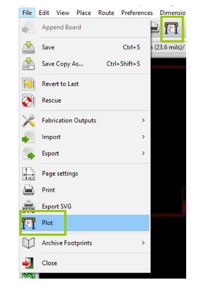
This will bring up the plot window. Select an output directory for your Gerber Files and select the following layers and options.
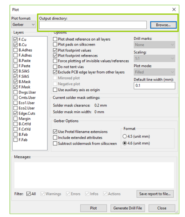
Please pay attention to the required layers, there should be 7 layers in total for typical two layer boards. If your boards are single or multi-layered, please select the necessary layers. Please note that all mechanical elements such as cut-outs and v-cuts should be drawn in the Edge.Cuts layer. Also, please ensure that you do not select the Include extended attributes option under Gerber Options. This will effectively convert the format of your Gerber files to X2, which not all our equipment supports.
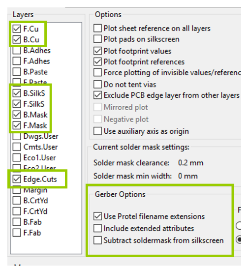
Click Plot and confirm that all the Gerber files were generated successfully.
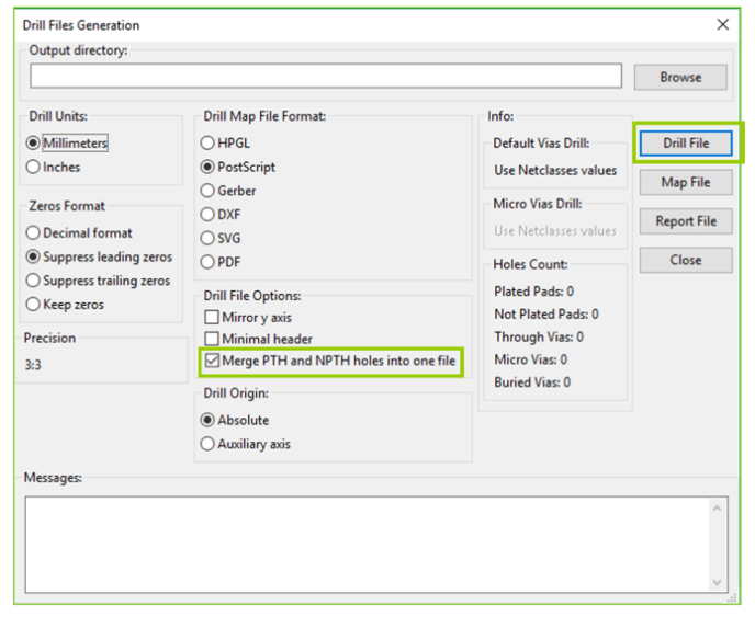
To generate the drill files, select the Generate Drill File button and this will open a new window. Click Drill File on the right and this is will export the drill file in Excellon format in your chosen directory.
We suggest to unclick “Merge PTH and NPTH holes into one file”.
Then it crucial to upload all the Gerber and Drill files (PTH and NPTH) onto the MacroFab platform.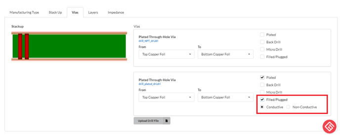
If there are vias in pad (VIP) that requires conductive or nonconductive fill it is crucial that the “Filled/Plugged” box is checked marked, then a new options will appear for selection (conductive or nonconductive). For nonconductive, the standard material is an epoxy, and for conductive the standard material is copper paste. The conductive selection will require a custom quote because not all PCB manufacturers carry copper paste.
In summary, breaking out the drill files into PTH and NPTH, and defining that the PTH drill files has vias in pad that require conductive/nonconductive fill helps out our manufacturing team tremendously.