The board outline gerber layer determines the extents of your PCB, allowing MacroFab to render your PCB correctly and to calculate the size of your PCB for proper pricing in the PCB interface.
Errors in the board outline can cause rendering issues and pricing problems. If this guide is not able to solve your issue, please contact support and we will do our best to rectify the problem. For more information on board outlines, check out this knowledge base article.
My PCB renders incorrectly
If your PCB renders but it has missing sections or slices then it is probably due to the board outline layer not being watertight, an edge of the outline might be missing, or the board outline is not fully connected to itself.
A quick check of the board outline layer in the Design Viewer will typically display the problem.
This problem is usually caused when drawing the board outline in your EDA tool and the line does not snap to the other line properly or part of the outline was deleted accidentally. Check to make sure all the points of your PCB’s board outline intersect and do not overlap, then check to make sure route outs or slots are also watertight.
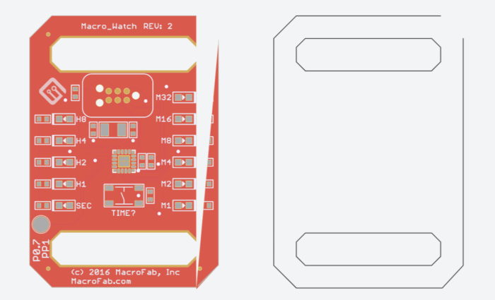 Missing edge in the board outline causing render issues.
My PCB renders incorrectly or is missing but the board layers look fine
This is usually caused by having overlapping lines and features in your PCB outline. Other possible causes of this problem are if a part in your EDA tool has the board outline layer defined and you drew over this area with the PCB board outline. This problem usually won’t cause your PCB to be manufactured incorrectly but it will prevent the ability to properly check part placements and check other layers of the PCB.
To fix this problem, check the design in your EDA tool and remove overlapping lines in the PCB outline.
If that is not possible then you should download your border file using the /files endpoint for the PCB and then view the gerber file in an offline gerber viewer like gerbv. With gerbv you will be able to remove gerber features and possibly fix your board outline layer. Stay tuned for a post on how to use gerbv to modify your gerber files.
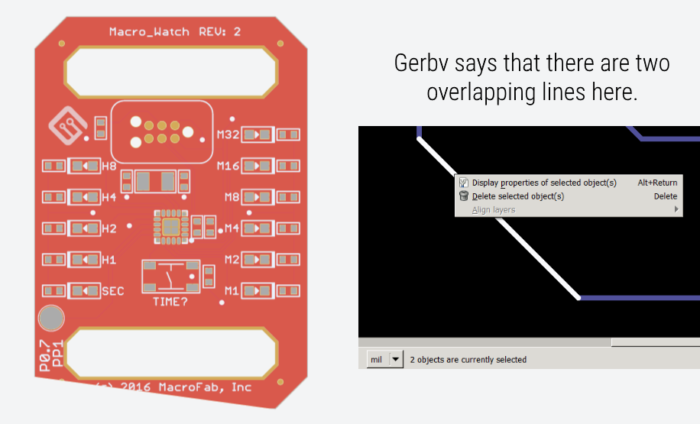 An extra or overlapping line in the board outline causing render issues
My PCB fails to render completely or does not look anything like my PCB
This is usually due to a.) not uploading a border file, b.) the platform incorrectly identified your board outline or c.) you mislabeled the border file. Check that the “Border and Cutouts” area of the PCB Layer Files are on the Design Viewer and make sure the files there look fine. If your border file is not there then check the top of the PCB Layer Files list in the “Unassigned Files” section as the platform might have placed it there.
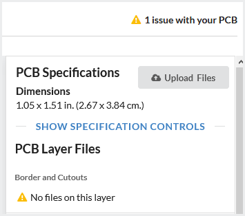 PCB viewer showing no border file.
My dimensions of the PCB are incorrect
The most likely cause of this is that your EDA tool generated additional information in the board outline layer. This can be title blocks, dimension lines, or layer description information. Some EDA tools add this information by default to the gerber outputs. Check out our EDA tool help area of the knowledge base to solve this problem.
You can typically delete this information from the gerber directly by using a gerber editor like gerbv.
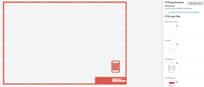 Border file with a frame embedded in it. This will cause rendering and dimension issues.
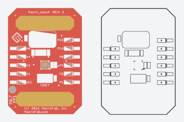
Boxes appear in my board outline layer and the PCB render looks weird
This is usually caused by another layer being merged into your PCB’s board outline. Most of the time this is an assembly drawing that your EDA tool has embedded into the board outline. Some EDA tools like Altium export the assembly drawing into the border outline by default. This is also common in ODB++ exporters. For a fix, check the EDA Tool help area of the knowledge base or you can try removing the assembly drawing information by using the /files endpoint to download your border file and a tool like gerbv.
Still having PCB Rendering Issues?
If you are still having PCB rendering problems with the interface please contact our support team. We will investigate the problem right away!