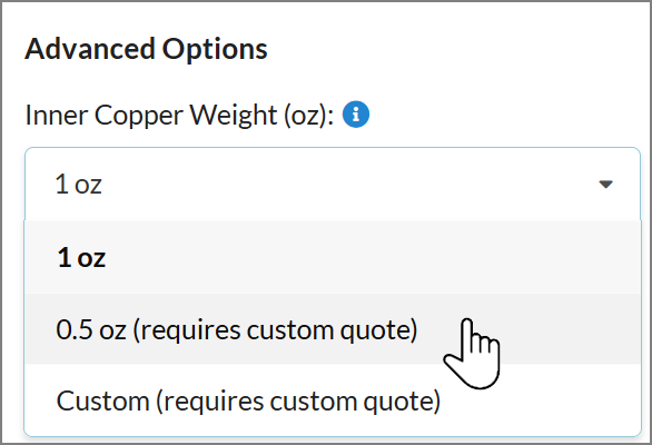
With the MacroFab Platforms interface designers can add custom PCB specifications.
After your PCB design files have been uploaded you can modify your PCB Specifications by navigating to the Specifications step tab in the PCB interface.
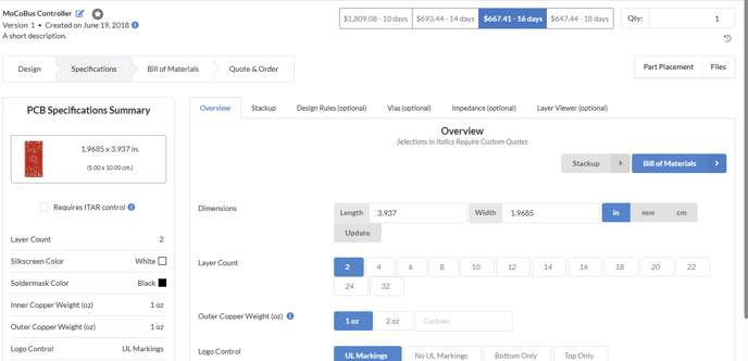
Specification Controls
Information regarding what PCB specifications MacroFab offers can be found in the PCB Specifications and DRC article.
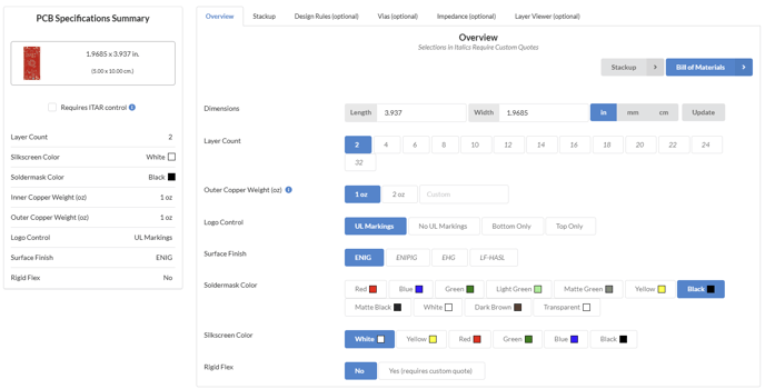
The majority of our PCB specifications are available for instant quoting however, some of our more advanced PCB specifications require custom quoting which you can request through the platform. These are denoted with (requires custom quote) in the platform.
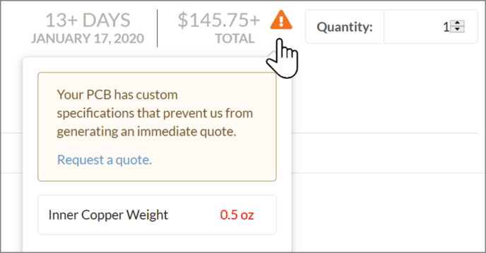
If you select a PCB Specification option that requires a custom quote the price tracker in the upper right of the platform will gray out and change. Here you can request a quote for your PCB and see what PCB specifications your PCB assembly is causing the platform from generating an instant quote.
Basic PCB Specifications
Layer Count
Change how many copper layers your PCB assembly has. For more information about layer stack up information check the PCB Layer Stack Ups article.
Soldermask Color
You can select from any of the following soldermask colors:
- Red
- Green
- Light Green
- Matte Green
- Blue
- Yellow
- Black
- Matte Black
- White
- Dark Brown
- Transparent
Changing the soldermask color will move your PCB Assembly into the Production Class Service. See the Prototype Class Vs. Production Class section below for more details.
Silkscreen Color
You can select from any of the following silkscreen colors:
- Red
- Green
- Blue
- Yellow
- Black
- White
Changing the silkscreen color will move your PCB Assembly into the Production Class Service. See the Prototype Class Vs. Production Class section below for more details.
Advanced PCB Specifications
Copper Weight for Inner and Outer Layers
You can select from 1oz to 0.5oz copper weight for inner layers and 1oz or 2oz for outer layers for your board. There is also the ability to specify a custom copper weight if needed.
Changing to 2oz copper weight incurs a minimum PCB charge and disables the extended manufacturing specifications, as we cannot produce the smaller 3mil traces with 2oz copper. See the PCB Specifications and DRC article for the differences in specifications between 1oz and 2oz copper weight.
Logo Control
Here you can specify if you want the PCB UL Markings, no UL markings, or specify which side you need the UL markings on.
Surface Finish
The default surface finish MacroFab supports is ENIG but you may use ENIPIG, EHG, or LF-HASL if needed. We do not support non-RoHS finishes. ENIG is generally the cheapest option.
Rigid Flex Support
Selecting this option will allows us to create a custom quote for your Rigid Flex PCB Assembly.
Manufacturing Type
The following manufacturing type options are available:
- Standard
Use standard manufacturing specifications, with a minimum trace width of 5mil and minimum drill of 12mil. This is the default specifications and do not have additional charges for choosing this option. - Extended
Decrease minimum trace sizes, annular rings, and edge clearance to 3mil. There is a one-time charge per order for selecting this option, which will be the same no matter how many boards you order. - Extended Drill
Decrease minimum drill size to 4mil. There is a one-time charge per order for selecting this option, which will be the same no matter how many boards you order. - Extended/Extended Drill
Combination of decreased minimum trace sizes, annular ring, and edge clearance with a decrease in minimum drill size to 4mil.
More information regarding what PCB specifications MacroFab offers can be found in the PCB Specifications and DRC article.
Stack Up
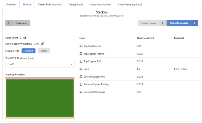
This tab allows you to choose from a variety of standard PCB stackups that MacroFab offers but also empowers you to customize the PCB stackup depending on the unique specifications for your PCB Assembly. Here you can also specify the PCB material used in the stackup. Our default material is FR4-TG175 (datesheet in this article) but you can select Rogers 4003C, Rogers 4350B, and Rogers 4450B.
Vias
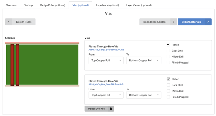
Have blind and buried vias? This tab will allow you to specify which of your Excellon drill files are through holes, plated, blind, or buried. For blind and buried vias, the PCB layers they span can also be specified. Back drill and Filled/Plugged via Excellon drill files can also be specified.
As you make changes to the vias, the illustration on the left will indicate how the vias will be prepared based on your specifications.
Impedance Control
Selecting this option enables impedance control for your order. You must provide additional information about your PCB when this option is selected. For more information about what is required see the article about Impedance Control.
Selecting impedance control on will add a one-time charge per order, which will be the same no matter how many boards you order.
Additional PCB Specifications
If you need more features for your PCB don't worry! The above specifications are for in platform instant or custom quotes. Other PCB features are possible. Contact our support team and we can get you a custom quote for your PCB quickly. Check our PCB Specifications and DRC page for more specifications our platform supports.
