Creating PCB Assemblies Automatically from your Eagle .BRD File
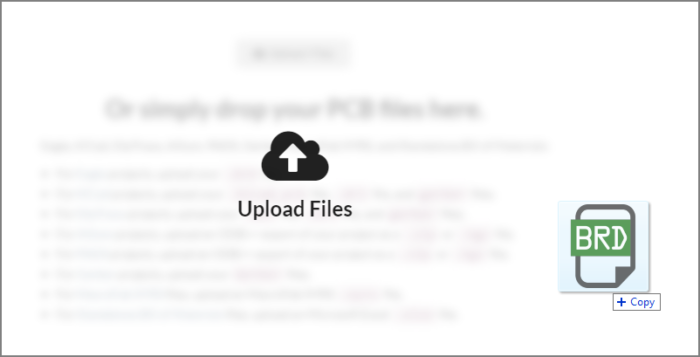
If you use the EDA tool Eagle to design your PCB Assemblies, the easiest method to upload your design files to MacroFab is to upload your Eagle .BRD file directly. The MacroFab platform will automatically extract the bill of materials, part placement data and the PCB Layer data from the .BRD file. In the PCB tab, simply drag-and-drop your .BRD file into the file upload target. Alternatively, you can click the Upload Files button on the right side of the screen. More information about uploading files to the platform can be found on the knowledge base article Creating a PCB and Uploading Design Files.
Once the files have been uploaded, you can verify that the .BRD file was properly converted into the PCB Layer data using the PCB viewer. Under the PCB Specifications Controls on the right side of the MacroFab platform you can check how many layers your PCB has which is automatically detected by the platform. The MacroFab Platform will create a file for each Layer that has information in it from the Eagle .BRD file. The platform may make files that are not necessary for making your PCB Assembly (Assembly or Notes) thus you will need to check them.
If you need to upload a different Eagle .BRD or any other files you can do so by using the Upload Files button or by dragging more files into the workspace. WARNING: Uploading another Eagle .BRD file to a PCB will wipe the PCB to a clean "state". Bill of Material information and placement data you may have entered will be lost!
Manufacturing Part Numbers and the Populate field
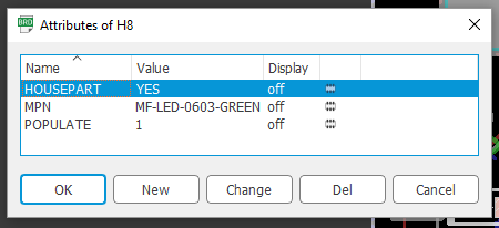
The MacroFab platform takes advantage of the Eagle Attribute system to allow users to specify a MPN (Manufacturing Part Number) and a Populate flag in the EDA tool. This allows additional information to be extracted automatically into the bill of materials. Eagle does not do this by default and will have to be added in. Our EDA Libraries for Eagle already have these attributes in them.
The attributes the MacroFab platform looks for are “MPN” and “Populate”. The MPN value can be filled with a part number and the Populate value has to be 0 or 1. Do Not Populate is 0 and Populate is 1.
If you do not know how to use Attributes in Eagle check out this engineering blog article that covers the topic.
Design Rule Checking in Eagle
It is important to run design rule checks (DRC) in Eagle before submitting your order. Design Rule Checks ensure that your design is within manufacturing specifications, while also identifying critical, but easy to miss, errors. To make life easier on you, we have prepared a number of design rule files for Eagle, which can be found on our GitHub page. Download the DRU file which corresponds to the number of layers in your board and the manufacturing specifications you are using.
Since the MacroFab Platform does not support blind and buried vias at this time, our DRC files only allow standard vias.
To perform a DRC check, first open your board layout in the Eagle editor, and then choose the DRC icon from the tool tray, or type drc in the Eagle command line. Once the DRC has loaded, you will see the following screen: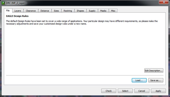
Press the Load button, and locate the DRU file you downloaded from our GitHub page. After executing the DRC, a DRC Errors screen will pop up. If any errors occur, you will need to correct them before submitting your files for production. If no errors are found, then you are ready to submit your files!
Creating PCBs Manually Using Eagle
If you’d rather not rely on the automatic extraction capabilities of the MacroFab platform, you’re not comfortable sending us your original source files, or if you’d like to make some changes to your data before uploading, you can export the Gerbers and XYRS (combined Placement and Bill of Materials data) file needed for production using the Eagle CAM and ULP files we provide.
Running Eagle CAM Manually
The CAM processor in Eagle generates the Gerber CAM files needed to manufacture the board. To generate the correct files for our process we have prepared CAM jobs that match to the number of layers in your design, and whether you’re using Eagle version 6.x or Eagle version 7.x. We have provided CAM jobs for 2, 4, 6, and 8 layer designs. For Eagle version 8+ use the 7.x versions.
Eagle Versions: Make sure you use the CAM job that matches to your version of Eagle, using a V7 job on Eagle V6, or vice-versa may result in silent failures to your design.
Once you’ve downloaded the correct CAM job file, click on the CAM processor icon in the tool tray. After the CAM job window opens, click on File and then Open to load the downloaded CAM file. Loading this file will properly set all Gerber options to work with MacroFab. After you have loaded the CAM job, click Process Job to generate the Gerber files. The output files will be saved in a subdirectory called “camfiles” inside your Eagle project directory. You may need to create this directory if Eagle can not.
Exporting XYRS (Placement) Data Manually
To export the placement and bill of materials data manually, we have provided a custom ULP script for Eagle to export the required data in the proper format. After it has been exported, you can open the generated .XYRS file in your favorite spreadsheet tool, as a tab-delimited file, make any changes, re-save it as a tab-delimited file, and then upload it directly to your PCB project. The script looks for two attributes on each part to fill out the Populate and MPN fields. These are optional.
Select the Run ULP… menu option from the File menu and find the MF_Eagle_Placement.ulp script you downloaded. This will generate a .XYRS file in the directory the .BRD file was in.
Cut Outs, Routs, and Slots
The MacroFab Platform currently only works with internal cut outs, routs, and slots that are defined as gerber features. To make this work in Eagle, cut outs, routs, and slots will need to be defined on the Dimension layer (20). This causes the cut outs, routs, and slots to be combined with the border layer gerber file. For more information about cut outs, slots, routes, and board outlines check out this engineering article.
Additional Eagle Questions?
If you have any other questions about creating a PCB Assembly with an Eagle .BRD file please contact our support team.