The required information to implement impedance controlled traces is the following: Which traces are impedance controlled Specifications of the traces Impedance Tolerance Trace Width Trace Spacing
If your PCB requires impedance controlled traces then additional PCB Assembly files are necessary to ensure the correct manufacturing of your PCBs. More information about what impedance control is can be found on our blog. If you are designing a new PCB and are looking for our default PCB Stackups check out this article.
Impedance Control Files
The required information to implement impedance controlled traces is the following:
- Which traces are impedance controlled
- Specifications of the traces
- Impedance
- Tolerance
- Trace Width
- Trace Spacing
The impedance controlled information can be shown in the form of an assembly document, provided as a separate gerber file, or as an image with the traces marked.
For example:
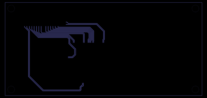
Traces to be controlled: Gerber File
Traces are to be 75 ohms ±15%.
Traces are 10mil and 10mil spacing
Layer is Top Copper
Impedance Control Tolerances
The default MacroFab impedance control tolerance is +/-10%. If tighter tolerances are required, these should be specified in the impedance control specifications.
Uploading the File
The impedance control file is uploaded to the MacroFab platform under the PCB Specifications Controls. See this article about Customizing PCB Specifications for more information.
Impedance Control Questions?
If you have any questions on how you get your PCB Assembly’s impedance control information in the correct format or uploaded correctly please contact our support team.